Background
General Multilin M60 is a motor protection relay. It also provides information on motor energy consumption and trouble shooting. Motor phasor diagram is a quick way to verify M60 wiring. If M60’s potential transformer (PT) and current transformers are Wye-Wye connection, voltage phasor diagram can be viewed as phase to ground voltage or phase to phase voltage. Using phase to ground voltage phasor, one can determine phase rotation and power factor quickly.
What is the correct phasor diagram for Open Delta – Open Delta PT wiring?
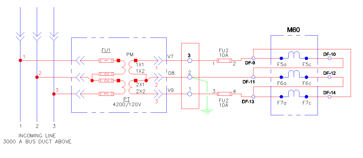
Current transformer (CT) wirings is shown below.
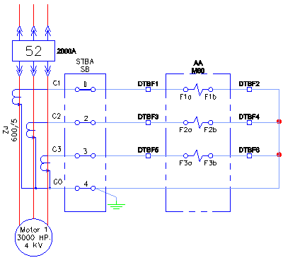
Potential Transformer wiring is shown below. It is open-delta to open-delta connection.
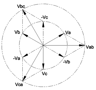
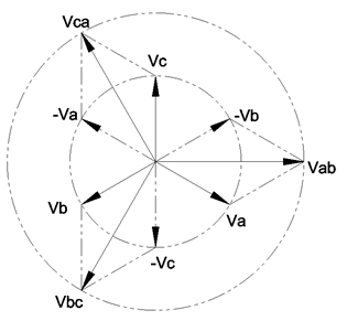
 Correct ABC phasor Diagram
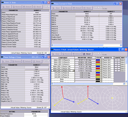
A M60 generated phasor diagram is shown below with power system as ABC. Notice that GE software does not generate phase to ground voltages (Vag, Vbg and Vcg). Ia lags Vab by 69.1 degree. Yet the motor’s power factor is 0.770 lag. Using the angle between Ia and Vab, the displacement power factor is 0.3567 (0.3567=cosine69.1). What is the problem here? The problem lies in M60 does not show phase to ground voltage. One has re-construct phase to ground voltage phasor with provided phase to phase voltage.
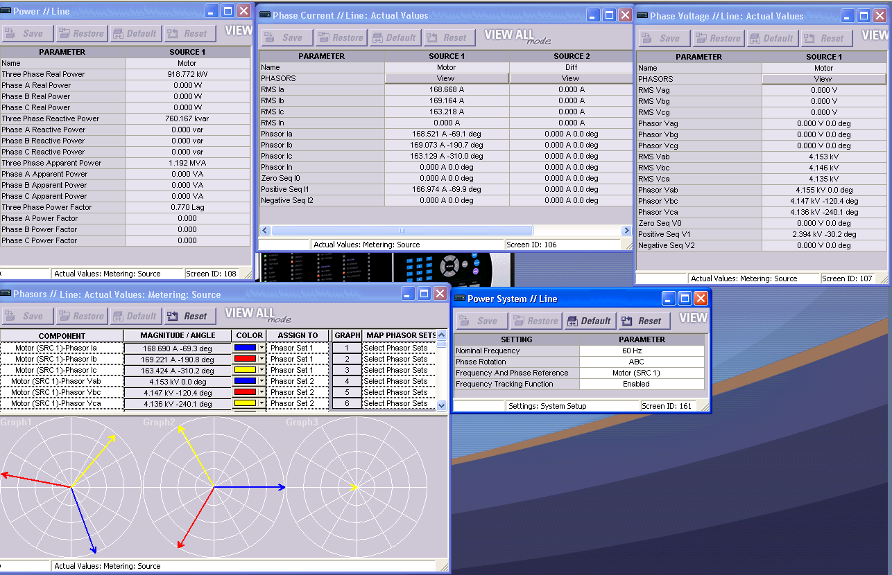
ABC’s rotation’s phase to ground voltage phasor is shown below. Notice that Va lags Vab by 30 degree in ABC rotation. Hence Ia lags Va by 39.1 (39.1 = 69.1 – 30). The displacement power factor is 0.776 lag (0.776 = cosine 39.1), which is very close to M60’s calculated power factor of 0.770 lag.
Correct ACB phasor Diagram
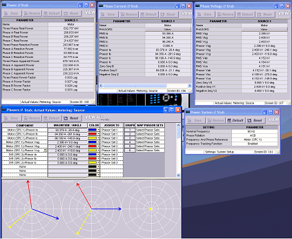
A M60 generated phasor diagram is shown below with power system as ACB. Ia leads Vab by 8.5 degree. Yet the motor’s power factor is 0.932 lag. To understand this, one has to re-construct phase to ground phasor diagram as well.

A phase to ground phasor diagram is created below. Notice that Va leads Vab by 30 degree for ACB rotation. Hence on Va leads Ia by 21.5 degree (21.5 = 30 – 8.5). The displacement power factor is 0.930 (0.930 = cosine21.5), which is also close to M60’s calculation.